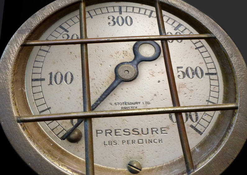
This tutorial will demonstrate how to use a combination of Normal Editor and Map Generation skills to draw a custom normal map
for an existing texture map. Before starting you should ensure that you have at least ShaderMap version 3.0.3 installed. In
this example we will be drawing a normal map for an analog pressure gauge. The link to the source texture and project files
can be found at the bottom of this page.
Step 1: Create an Empty Project and Load the Texture
Open the ShaderMap application. From the Start screen, click the Advanced Setup button (bottom-right of the window). This will
take you to an empty project and display the Add Node dialog. Select Source: Color Texture then load the Gauge Texture image file.
Once the texture is loaded you will see a thumbnail image of it in the Project Grid. Save the project to file, name it
Gauge_Normals or Meter_Normals.
 Step 2: Generate the Initial Normal Map
We are going to create a normal map that is the same size as the original source texture. In this step we will first create a
displacement map from the diffuse texture, isolate the outer ring with a gray-scale mask, then generate a normal map from the
displacement map.
Move your mouse over the empty Project Grid cell below the source texture thumbnail. Click the + (plus) button to bring up the
Add Node dialog. Select Map: Displacement ( Diff ) to add a displacement map (from diffuse) to the Project Grid. Once the map
is added a displacement map is generated from the diffuse texture. The default settings for the displacement map will do just fine.
We want to isolate the outer ring of the gauge so we can generate normals just for that part of the map. Select the displacement
map in the Project Grid and in the Map Properties section, click the Load Mask button. Locate and find the black & white mask
image file (download with the project below).
Move your mouse over the empty Project Grid cell to the right of the displacement map, click the + (plus) button and add Map: Normal ( Disp ).
Once added, select the normal map and ensure the normal map’s source input is on the displacement map. You can left mouse
drag-and-drop the source marker to any map that isn’t logically impossible. Add the map mask to the normal map just as you did with
the displacement map. This will help tighten up the edges of the normals.
 Step 3: Create a Standard Material for Visualization
Go to the Material Visualizer (Press M on the keyboard). Select Geo: Dynamic Plane under the main Visualizer window. Bring out the
Material Editor (arrow on the right of the window) if it isn’t already out. Move your mouse over an empty cell in the Material Grid,
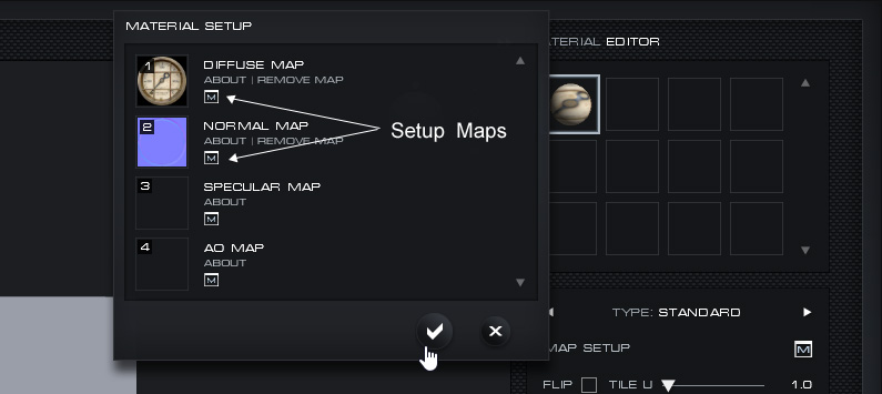
click the + (plus) button then select Standard from the list. Setup the Diffuse Map and the Normal Map by clicking the “M” button
located next to each one on the Material Setup dialog. Press Enter to exit the dialog.

Left mouse drag-and-drop the material onto the Dynamic Plane geometry. You are now setup to view changes as they are made to the normal map.
* Remember to save your project from time-to-time.
Step 4: Send the Normal Map to the Editor and Setup the Overlay
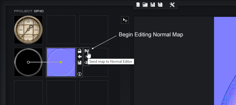
Select the normal map in the Project Grid. All normal maps can be sent to the Normal Editor by clicking the “N” button in the
node controls (right side of thumbnail). Click the “N” button now. The normal map is displayed in the Normal Editor interface.
At the bottom left of the Normal Editor preview window you will see an “M” button. This button allows you to setup an overlay
image to be rendered on top of the normal map. Press “M” and select the original source texture from the popup dialog. You can
now adjust the opacity of the overlay and toggle it with the check box.
 Step 5: Draw the Gauge Bar (Face Guard) Normals
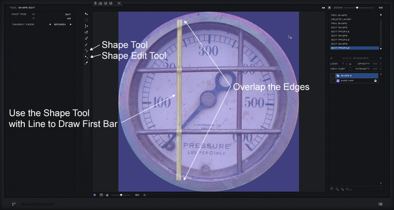
Ensure the overlay is on and set with an opacity of 50%. Select the Shape Tool in the toolbar. In the Tool Properties select
Pen and enable line with a width of 28 pixels. Draw the left vertical bar by first clicking above it then below it so the
line shape extends onto the outer ring (we will crop this later). You should now have a line shape layer with flat normals,
it may be hard to see. Select the Shape Edit Tool in the toolbar then click on the line shape to edit it. You can use the
Shape Edit Tool to add and delete knots from the shape as well as move existing knots and knot weights.
Once you have the line completely covering the bar in the overlay image it is time to add surface normals to the shape.
Right click the shape layer in the Layer Control (right panel). Select Layer Profile from the context menu. This will
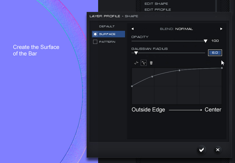
bring up the Layer Profile dialog. Select Surface on the left of the dialog. This will immediately generate normals across
the surface of the shape layer. Use the curve control to shape the height of the surface of the layer from outside edges
(left curve graph) to middle inside (right curve graph). Click and drag knots in the curve or click anywhere on the curve
to add a new knot. Knots can be linear (straight lines) or curved. We want the bar to have a nice rounded surface so we set
the graph to look like the following:
Now do the same for the remaining three bars. If you make a mistake simply undo the action by selecting an event in the
History Control list or by using the keyboard shortcut Ctrl+Z.
The horizontal bar layers will need to be ordered above the vertical bar layers in the Layer Control to match the source texture.
To change the order of layers, drag layers up and down in the Layer Control. To save time you can copy and paste the Layer
Profile from the first shape layer. Right-click the first shape layer and select Copy Layer Profile. Right click on any, or all,
of the other three layers then select Paste Layer Profile. To select multiple layers hold Ctrl while clicking on layers. Once
completed you will have something that looks like this:
 Step 6: Crop the Gauge Bars
The next step is to crop the bar shape pixels to the edge of the outer ring. Select all four of the bar shapes. Select the top
shape layer in the Layer Control, press and hold the Shift Key, then select the bottom layer. You can also use the Transform
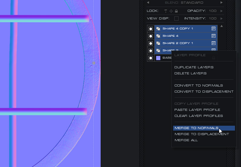
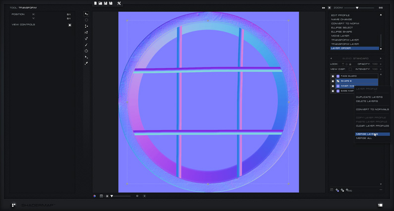
tool to rectangle select the layers. Once they are all selected, right click any of them in the Layer Control and select Merge
to Normals. This will convert all of the Shape layers to Rasterized Normals while combining them into a single layer. We do
this so that individual pixels can be deleted from layer which is not possible on Shape layers.
Double click the merged layer name to rename it Face Guard.

Choose the Select Tool from the toolbar. In the Tool Properties panel select Ellipse shape and ensure Anti-Alias is enabled.
Use the selection tool to create a selection that fits inside the gauge’s outer ring. Once you are happy with the selection
use the keyboard shortcut Ctrl + Shift + I to invert the selection.

Ensure the Face Guard layer is selected in the Layer Control then press the Delete Key to remove the overlapping pixels. See below:
 Step 7: Draw the Inner Wall Normals
On the inside of the outer ring begins a section of metal that descends towards the face of the gauge. We are going to create
the normals for this section using an Ellipse Shape and a Surface Profile. Select the Shape Tool on the toolbar and ensure it
is set to draw an Ellipse shape type that is not a line (solid shape). Draw an ellipse Shape Layer that covers the inside of
the gauge. Use the Transform Tool to scale it to fit.
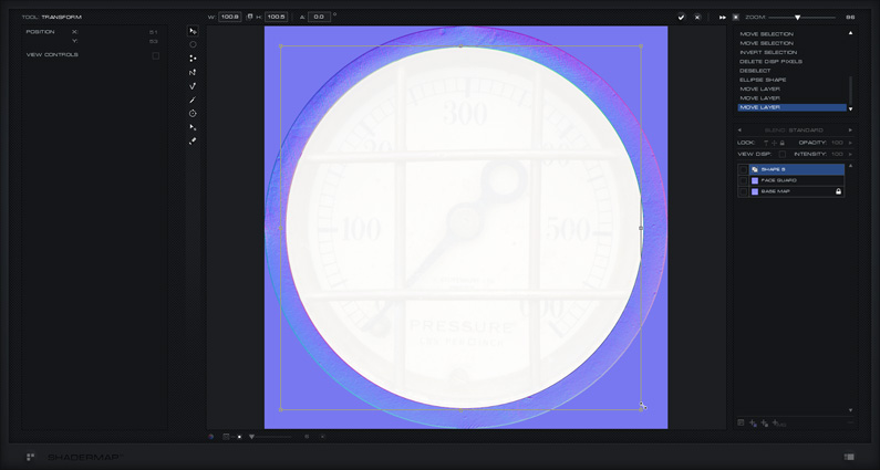
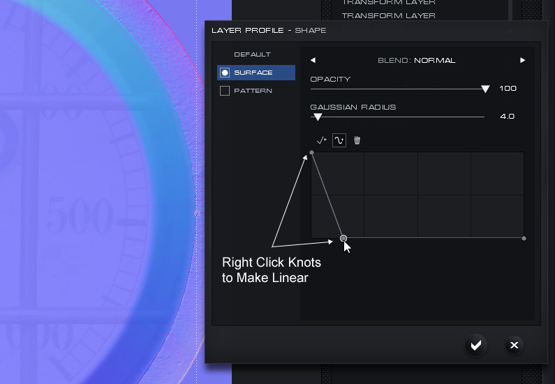
Select the layer in the Layer Control and open the Profile dialog. Add a surface profile that descends linearly as shown
below. Use a bit of Gaussian Blur to get a smooth result.
Use the Shape Ellipse Tool to draw an ellipse Shape Layer over the previously created layer and fitting perfectly over the
face of the gauge. Use the Transform Tool to make adjustments. This layer is simply to give flat normals to the inside of the
face and create sharp edges on the previously created normals.
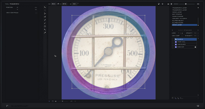
Merge the layers to Normals and rename the layer Inner Wall.
 Step 8: Draw the Screw Head Normals
There are two screw heads on the gauge. The one at the base has a flat slot diagonally across it and the other is smooth on it’s
surface. Can you guess how we are going to create the normals? That’s right, ellipse Shape Layers with Surface Profiles. Use the
Shape Tool to draw ellipse shapes over the bottom screw. Use the Transform tool to scale it to fit. Rename the layer Screw Head.
Apply a round Surface Profile with the settings shown below:
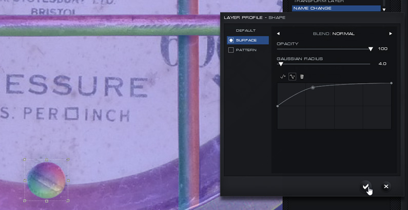
Right click the layer in the Layer Control. Select Duplicate Layer from the context menu. Drag the duplicated layer over to the
left screw head and use the Transform Tool to fit it to the pixels.
The next step is draw the groove in the bottom screw. Use the Shape Tool with Pen shape and line enabled with a width of 8-9
pixels. Draw a line across screw head to match the slot in the texture. Ensure the line is extended beyond the head as shown.
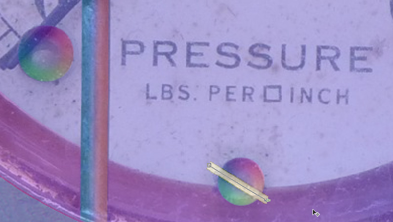
Apply a Surface Profile to the groove with the following settings:

Convert the groove layer to Normals by right clicking the layer and selecting Convert to Normals. Rename the layer to
Screw Groove. Next use the Select Tool to draw an ellipse over the bottom screw head, invert the selection then delete
the pixels that extend over the edges of the screw.

Ensure that the layers are ordered correctly. If the groove is under the screw head it will not be visible. Drag
layers up and down in the Layer Control to change their order.
Use the E key at any time to bring up an external window with the Material Visualizer in it. This is good to do from
time-to-time so that you can see exactly what your normals will look like when rendered in a 3D environment.
Step 9: Draw the Gauge Hand Normals
Now to draw the gauge hand. To do this we will use the Shape Tool with Pen Shape and line disabled (solid shape).
See below how the shape is supposed to look on a first attempt. The Shape Edit Tool is used to fine tune the shape
afterwards.
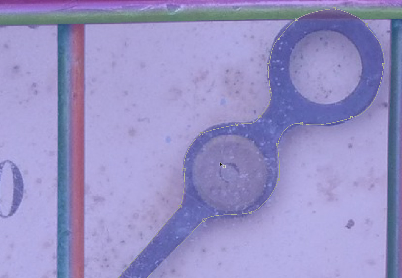
This might take you a few attempts. Start by making the first knot then on the second knot click then hold the
mouse while dragging away from the knot. This will create a curve knot with control points, these can be modified
later with the Shape Edit tool. Any knot can be linear or a curve. Knots can be configured with the Shape Edit
tool by first selecting a knot then changing the knot settings in the Tool Properties. Rename the layer to be
called Arm.
The final Arm shape should look like this:

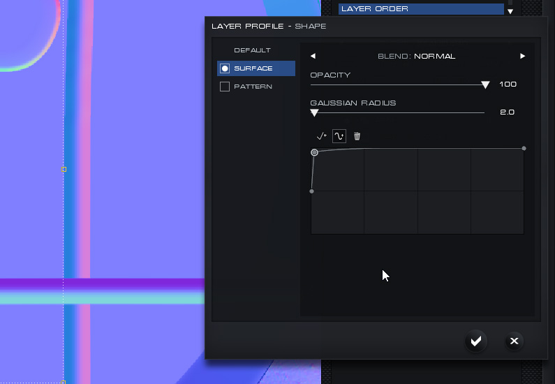
Add a Surface Profile to the Arm layer with the following settings. The idea is to make it look like it is rising
up off of the surface of the gauge face:
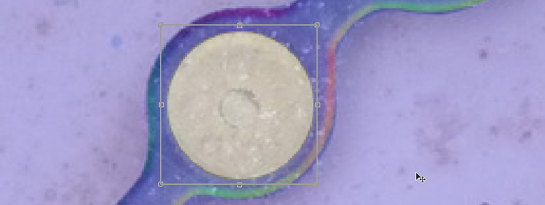
Draw and fit a filled ellipse shape over the center of the arm. Rename the layer Arm Pivot. Apply a Surface Profile
so it appears to be rising up from the arm. See below:

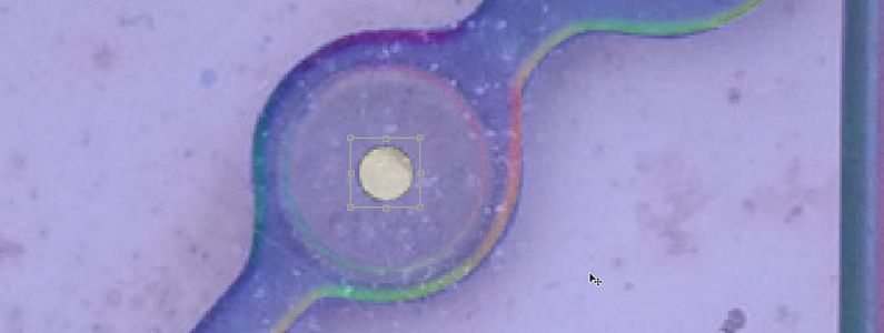
Draw and fit a smaller filled ellipse shape over the center of the Arm Pivot. Rename the layer Arm Pivot Center.
Apply a Surface Profile so it descends into the Arm Pivot. See below:
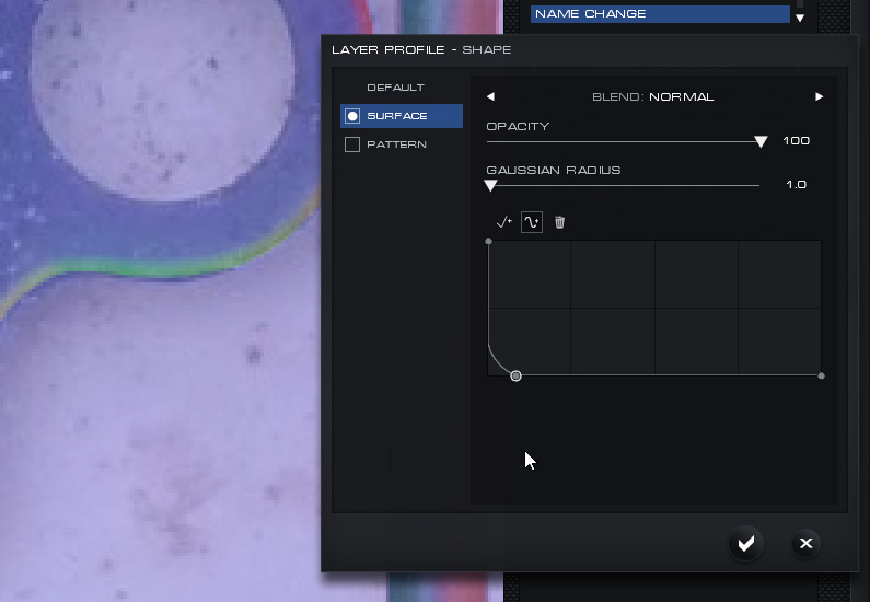
Finally draw and fit a filled ellipse over the back end of the Arm layer. Rename the layer Arm Eye. It should have
a Surface Profile so that it descends into the Arm layer as shown below:

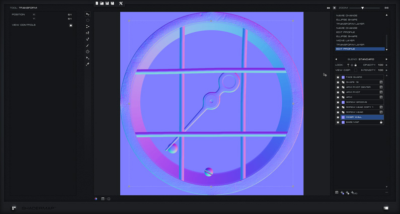
Here is what the Normal Map should look like at this point:
 Step 10: Generate a Detail Normal Map
The next step is to create a detail normal map. This will be used to give additional detail to the face of the
gauge. Exit the Normal Editor by pressing the Main Interface button located at the bottom-right of the application
window. You are now back to the Main Interface and should see the Project Grid just as you left it.
Add a new node Map: Specular ( Disp ). This will generate a detail specular map from a displacement map but we are
going to use the source color texture as the input. Once the Specular map is added select it then drag its input
line to the original source color texture of the gauge.
Next add another node Map: Normal ( Disp ). This will generate a normal map from displacement but we are going to
use the generated specular map as the input. Once the Normal map is added select it then drag its input line to
the previously created specular map. Set the intensity of the Normals to 10.

Send the newly generated Normal map to the Normal Editor. Do this by pressing the “N” button next to the
selected map’s thumbnail in the Project Grid. Select the Vector Brush Tool from the toolbar. Set it up to
have the following settings:

Make sure the Base Layer is selected in the Layer Control then begin painting over the bar normals, the
arm normals, and the outer ring. We are painting over these normals because we do not want them to bleed
out under the normals layers we have already created. The final result should look something like the
image below:
 Step 11: Copy the Detail Normals to the Editor and Blend
You should still be in the Normal Editor with the painted detail normal map. Choose the Select Tool
from the toolbar and ensure rectangle shape is chosen. Select the base layer in the Layer Control. Use
the keyboard shortcut Ctrl + A to select all pixels in the layer. Press Ctrl + C to copy the pixels to
the clipboard. Now exit the Normal Editor and return to the Main Interface.
Select the other (main) Normal Map in the Project Grid and send it to the Normal Editor. Press Ctrl + V
to paste the copied layer pixels as a new layer. Rename the layer to Detail. Order (drag) the layer in
the Layer Control to be just above the Base Map right near the bottom. Next select the Detail layer and
set the Blend Mode to UDN. You can also adjust the intensity of the Detail layer normals to around 50%
which will give a nicer result.
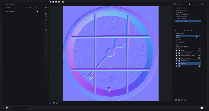
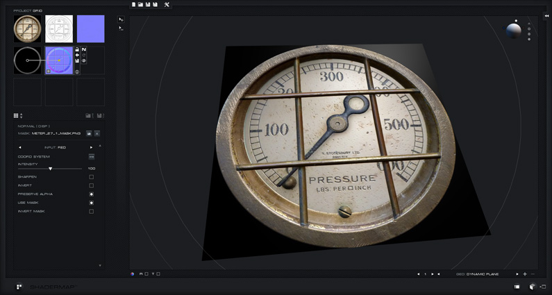
Exit back to the Main Interface and see the results in the Material Visualizer. Try moving the white
light in the Visualizer scene to see how light plays off the surface of the gauge normals. Disable the
diffuse map in the Standard Material to display only normals.

Download Resources
The SM3 Project File and Mask can be downloaded here:
meter_normals_project
Note: This older project file will use legacy map plugins when loaded with SM4 and up.
The source image is located here:
http://www.mb3d.co.uk/…/meter_27_1.jpg
Find more great free and seamless textures at:
http://www.mb3d.co.uk/


